Total Flare System Design & Analysis Software

http://www.flaretot.com/
+ نوشته شده در دوشنبه ۲۹ خرداد ۱۳۹۱ ساعت 10 توسط فرامرز-رضا
|
http://www.flaretot.com/


کتاب طراحی فلر منتشر شد ....
انتشارات اندیشه سرا


عکس ماهواره ای از فلرهای کشورهای حوزه خلیج فارس ۲۰۰۹


The flare is a last line of defense in the safe emergency release system in a refinery or chemical plant. It uses to dispose of purged and wasted products from refineries, unrecoverable gases emerging with oil from oil wells, vented gases from blast furnaces, unused gases from coke ovens, and gaseous water from chemical industries. Flares are also used for burning waste gases from sewage digesters process, coal gasification, rocket engine testing, nuclear power plants with sodium, water heat exchangers, heavy water plants, and ammonia fertilizer plants. The flare provides a means of safe disposal of the vapor streams from its facilities, by burning them under controlled conditions such that adjacent equipment or personnel are not exposed to hazards, and at the same time obeying the environmental regulation of pollution control and public relations requirements. The chemical process used for flaring is a high temperature oxidation reaction to burn combustible components, mostly hydrocarbons, or waste gases from industrial operations. In combustion, the gaseous hydrocarbon (natural gas, propane, ethylene, propylene, butadiene, butane and etc) reacts with atmospheric oxygen to form carbon dioxide (CO2) and water. Several by products formed will be carbon monoxide, hydrogen and others dependent upon what is being burned. Efficiency of hydrocarbon conversion is generally over 98%.
Flare Type: Flares are generally categorized in two ways:
Selection of ground or elevated flare type is influenced by several factors, such as availability of space; the characteristics of the flare gas (composition, quantity and pressure); economics; investment and operating costs; public relations and regulation.

Self Supported Flare stacks are normally used for flare system and offer a good alternatives to guy wire supported, or derrick-supported structures, for flares up to 40 meters tall, for flare more tall it cost is more expensive than other design, because it need greater material to ensure structural integrity for static conditions. But for this kind of structures the condition to be taken into account is the dynamic behaviour. In fact, due to elevated flexibility, in resonance condition, even low wind speed can cause instability on the structure. TechEngineering team is strongly specialized in this field and has the necessary competences to suggest the best way and the most suitable tools to be used to prevent the occurance of this effect. Selection of the riser material, included KO Drum and/or Water Seal, is in accordance to relevant specifications, while shell thickness is calculated from both mechanical and structural point of view. Particular attention must be reserved to the anchor bolts. In fact, because the self-supported flare can be subject to dynamic actions, the anchor bolts must be pre-tensioned. TechEngineering, in this case, suggests to use anchor bolts with sleeve which allows their pretension without excessive stress on the concrete. The design allows to integrate the K.O. Drum and / or the Water Seal in the base area of the flare. Top maintenance platform for the tip can be reached about ladders and intermediate platforms. Erection on site is limited by large prefabrication in workshop. The self-supported flare can be accessoried with a davit which allows the flare tip to be lowered to grade for inspection and maintenance and to be successively lifted in its position.


ENGINEERING STANDARD FOR PROCESS DESIGN OF FLARE AND BLOWDOWN
برای دانلود کلیک کنید ....
دانلود استاندارد طراحی سیستم فلر و بلودان
مدیر پیشنهادات شرکت ایرتیک به عنوان یکی از شرکتهای پیمانکاری طرح آماک در گفت وگو با خبرنگار اقتصادی مهرگفت: با اجرای طرح آماک ماهانه 238 میلیون فوت مکعب گازهای همراه هفت حوزه نفتی جمع آوری می شود.
مسعود نبوی اضافه کرد: دراین طرح گازهای ترش لایه های بنگستان شامل مخازن نفت اهواز، آب تیمور، منصوری ، کوپال و مارون جمع آوری می شود .
وی با اشاره به صرفه اقتصادی این طرح گفت: این طرح تا 20 سال آینده بیش از3 میلیارد دلار ارز را عاید کشورمی کند .
افزود: ارزش این قرارداد 300 میلیون دلار بوده و شرکت ملی نفت کارفرمای آن و این طرح برای اولین بار است که به سرپرستی یک شرکت ایرانی انجام می شود.
وی که از پیمانکاران این طرح محسوب می شود گفت: در طرح آماک می توان از ظرفیت مازاد کارخانه های گاز و گاز مایع 700 و 800 در منطقه خوزستان برای فرآورش گازغنی تولیدی و تولید مایعات گازی شیرین استفاده کرد .
| طرح آماک طرحی برای جمع آوری گازهای همراه چندمیدان نفتی و پیش گیری از انتشار موادآلاینده است. در حال حاضر گازهای ترش همراه نفت تولیدی مخزن بنگستان میدان های آب تیمور ،منصوری ،مارون اهواز و کوپال به علت فقدان تاسیسات لازم سوزانده می شود . طرح آماک به منظور جمع آوری و استفاده از این گازها و جلوگیری از هرز رفتگی و آلودگی محیط زیست اجرا می شود . واژه آماک از بهم پیوستن حروف اول آب تیمور ، منصوری ، مارون ، اهواز و کوپال ساخته شده است . 1 – اهداف کلی طرح 1-1- جلوگیری از سوختن گاز ترش همراه نفت و پیشگیری از انتشار مواد آلاینده . 2 -1- تولید مایعات گازی شیرین (NGL) 3-1- تولید گاز سبک شیرین برای مصارف صنعتی 4-1- افزایش توان تولید نفت خام از راه برگشت مایعات گازی ترش در ایستگاههای تراکم گاز به واحدهای بهره برداری 5-1 - انتقال گازهای اسیدی تفکیک شده در پالایشگاه شیرین سازی طرح به مجتمع پتروشیمی رازی برای فرآورش و تولید گوگرد صادراتی 2 – ویژگی های طرح از طرح های برنامه پنج ساله دوم (78 – 1372) توسعه اقتصادی ، اجتماعی و فرهنگی کشور به شمار می رود و با استفاده از تسهیلات بیع متقابل به اجرا درآمده است. در خرداد ماه 1379 این طرح به صورت کلید در دست به کنسرسیوم ایریتک – ایراسکو واگذار شد.ین کنسرسیوم از یک شرکت ایرانی و یک شرکت ایتالیایی تشکیل شده است . مدیریت ،مهندسی ، برنامه ریزی و کنترل پروژه ،کلیه عملیات اجرایی ، ساخت تجهیزات در داخل کشور و پیگیری امور مربوط به ترخیص کالاهای تدارکات خارج و حمل کالا به کارگاه ها بر عهده شرکت ایرانی ایریتک در ایران است .خرید و تامین تجیزات ساخت خارج از کشور و حمل آن تا مبادی ورودی و همچنین فراهم کردن امکان دسترسی به دانش فنی ویژه پروژه بر عهده شرکت ایساکو است . کارفرمای طرح ، شرکت مهندسی و توسعه نفت (OIEC) وابسته به شرکت ملی نفت ایران است . مسئول تامین مالی طرح شرکت نفت ایران اینترترید (NICO ) ثبت شده در جرسی بریتانیا است که تمام سهام آن به شرکت ملی نفت ایران تعلق دارد . 3 – محل اجرای طرح واحدهای بهره برداری و تفکیک کننده گازی همراه نفت مخازن بنگستان مرتبط با طرح در حوالی مناطق اهواز و مارون قرار گرفته است . با توجه به جنبه های فنی ، اقتصادی و ایمنی ، محل ایستگاه های تراکم (کمپرسورها )و واحدهای نم زدایی گاز در نزدیکی واحدهای بهره برداری مربوطه در نظر گرفته شده است . 4 – ایستگاه های تقویت فشار و نم زدایی گاز هفت ایستگاه تقویت فشار و نم زدایی در مجاورت واحدهای بهره بردای شماره 1 ،2 ،3 اهواز ،آب تیمور منصوری کوپال و واحدهای بهره برداری شماره 3 مارون در نظر گرفته شده است . گاز ها به همراه نفت حاصل از چهار مرحله تفکیک با خطوط لوله به ایستگاه های تقویت فشار منتقل می شود . گاز هر مرحله تفکیک ، پس از تراکم و خنک شدن با خنک کن هوایی با گاز مرحله بالاتر خطوط و وارد مرحله تراکم بعدی می گردد . این فرایند تا آخرین مرحله تراکم ادامه می یابد . گازهای خروجی از آخرین مرحله تراکم پس از خنک شدن و عبور از مخزن مایع گیر ، به واحد نم زدایی و گاز خشک خروجی به پالایشگاه شیرین سازی گاز ارسال می شود. 5 – پالایشگاه شیرین سازی این پالایشگاه درنزدیکی کارخانه های گاز و گاز مایع 800/700 احداث شده است . گازهای خشک ورودی با چند راهه ورودی جمع آوری و به سیلابه گیرهای وروردی هدایت و سپس به دو ردیف مشابه واحد شیرین سازی ارسال می شود . در برج جذب ، گاز ترش ورودی در تماس با محلول دی اتانول آمین (DEA) قرار می گیرد و گازهای اسیدی و ترکیبات گوگردی کاهش می یابد . گاز شیرین خروجی به کارخانه های گاز و گاز مایع 700 و 800 ارسال می گردد . 6 – ایستگاه تراکم گازهای اسیدی این ایستگاه دارای سه ردیف و هر ردیف شامل 4 مرحله تراکم است . گاز خروجی از آخرین مرحله تراکم پس از خنک شدن در خنک کن هوایی و عبور از ظرف مایع گیر به واحد نم زدایی هدایت می شود . نم زدایی با غربال مولوکولی انجام می گیرد ،گازهای اسیدی پس از نم زدایی به مجتمع شیمیایی رازی حمل می شود. 7 - خطوط لوله انتقال گاز 1 – 7 – شبکه خطوط لوله طرح آماک از 11 رشته خط لوله با قطرهای 4 تا 81 اینچ و طول 175 کیلومتر تشکیل شده است . 2 – 7 – انتقال گاز ترش از ایستگاه های تراکم گاز به پالایشگاه شیرین سازی 3 -7 – انتقال مایعات گازی از مایع گیرهای پالایشگاه شیرین سازی به واحد بهره برداری شماره 1 اهواز 4 – 7 – انتقال گازهای پالایش شده به کارخانه های گاز و گاز مایع 700 و 800 5 -7 – خطوط لوله انتقال گازهای اسیدی از پالایشگاه شیرین سازی به مجتمع شیمیایی رازی به قطر 12 اینچ و طول حدود 95 کیلومتر.
|
| |
امكانسنجي كاهش و يا بازيابي گازهاي ارسالي به فلر اصلي واحد الفين پتروشيمي اميركبير
جهت كسب اطلاعات تكميلي مي توانيد با شركت پژوهش و فناوري پتروشيمي تماس حاصل فرماييد

FG International erects a new flare stack for Valero in Aruba
FG International Holland BV, the Dutch Special Lifting company, has been awarded a major turnkey contract by North America’s largest independent petroleum refiner Valero Energy Group.
The project involves the dismantling and removal of the old flare stack, a 90m high tower with a 11.5m x 11.5m base. At the same location a new unit will be build up.
The limited space near the waterfront created an extra challenge that mainly triggered the used erection method. And the fast delivery to shorten the shutdown time further cemented the deal between Valero and FG.
FG International has worldwide applied various methods for flare stack erection throughout the years.

منابع آلایندهها
هوا دارای آلایندههای طبیعی نظیر هاگهای قارچها ، تخم گیاهان ، ذرات معلق نمک و دود و ذرات غبار حاصل از آتش جنگلها و فوران آتشفشانهاست. همچنین هوا حاوی گاز منو اکسید کربن تولید شده به شکل طبیعی (CO) حاصل از تجزیه متان (CH۴) و هیدروکربنها به شکل ترپنهای ناشی از درختان کاج ، سولفید هیدروژن (H۲S) و متان (CH۴) حاصل از تجزیه بیهوازی مواد آلی میباشد.
منابع آلایندهها را بطور کلی میتوان در چهار گروه اصلی طبقه بندی کرد: حمل و نقل متحرک ، احتراق ساکن ، فرآیندهای صنعت ، دفع مواد زاید جامد .
هیدروکربنها
ترکیبات آلی که تنها دارای هیدروژن و کربن هستند به نام هیدروکربن نام میگیرند که بطور کلی به دو گروه آلیفاتیک و آروماتیک تقسیم میشوند.
هیدروکربنهای آلیفاتیک
گروه هیدروکربنهای آلیفاتیک شامل آلکانها، آلکنها و آلکینها هستند. آلکانها عبارتند از: هیدروکربنهای اشباع شده که در واکنشهای فتوشیمیایی اتمسفر نقش ندارند. الکنها که معمولا به نام اولفینها خوانده میشوند. اشباع نشده هستند و در اتمسفر از لحاظ فتوشیمیایی تا حدودی فعالاند. این گروه در حضور نور خورشید با اکسید نیتروژن در غلظتهای زیاد واکنش نشان میدهند و آلایندههای ثانوی مانند پراکسی استیل نیترات (PAN) و ازن (O۳) را بوجود میآورند. هیدروکربنهای آلیفاتیک تولید شده تا حدود (۳۲۶ mg/m۳) برای سلامت انسان و جانوران خطرساز نیست.
هیدروکربنهای آروماتیک
هیدروکربنهای آروماتیک که از لحاظ بیوشیمیایی و بیولوژیکی فعال و برخی از آنها بالقوه سرطانزا هستند یا از بنزن مشتق شدهاند و یا به آن مربوط میشوند. افزایش میزان ابتلا به سرطان ریه در نواحی شهری به هیدروکربنهای چند هستهای خارج شده از اگزوز اتومبیلها نسبت داده شده است. بنزوپیرین سرطانزاترین هیدروکربنهاست. بنزاسفنانتریلین ، بنزوانتراسین و کریزین هم مواد سرطانزای ضعیفاند.
منابع هیدروکربنها
میللنگها و کاربراتورها ، بیشترین درصد آزادسازی هیدروکربنها را به خود اختصاص دادهاند تجهیزات سوزاننده مکمل که با کاتالیست کار میکنند هیدروکربنها آزاد شده و منو اکسید کربن را سوزانده و تولید CO۲ و آب مینمایند.
تکنولوژی کنترل هیدروکربنهای متصاعد شده از منابع ساکن
تکنولوژی کنترل هیدروکربنهای متصاعد شده از منابع ساکن عبارتند از: خاکستر سازی ، جذب ، تراکم و جایگزین نمودن سایر مواد.
فرآیند خاکسترسازی با دستگاههای سوزاننده مکمل و دستگاههای سوزاننده مکمل کاتالیستی صورت میگیرد. جذب سطحی توسط کربن فعال صورت میگیرد و جذب هیدروکربنها بوسیله یک محلول شوینده در برجهای سینیدار ، شویندههای جت و برجهای آکنه ، برجهای پاشنده و شویندههای ونتوری صورت میگیرد.
منو اکسید کربن
گاز منو اکسید کربن بیرنگ ، بیمزه و بیبو است و در شرایط عادی از لحاظ شیمیایی بیاثر و طول عمر متوسط آن در اتمسفر حدود ۲/۵ ماه است. در حال حاضر مقدار منو اکسید کربن در اتمسفر بر روی اموال انسانی ، گیاهان و اشیا بیاثر یا کماثر است در غلظتهای زیاد منو کسید کربن به علت تمایل زیاد به جذب هموگلوبین میتواند در متابولیسم تنفسی انسان بطور جدی اختلال ایجاد نماید. غلظت منو اکسید کربن در نواحی متراکم شهری که ترافیک سنگین و حرکت خودروها کند است به میزان قابل توجهی افزایش مییابد منابع کربن ، منو کسید کربن طبیعی و انسانی هستند. طبق گزارش آزمایشگاه ملی آرگون در اثر اکسیداسیون گاز متان حاصل از مرگ گیاهان سالانه ۱۳/۲ میلیون تن CO وارد طبیعت میشود. منبع دیگر تولید این ماده متابولیسم انسانی است بازدم شخصی که در حال استراحت است بطور تقریبی حاوی CO۱ppm است.
اکسیدهای گوگرد
این اکسیدها شامل ۶ ترکیب مختلف گازی هستند: منو اکسید سولفور (SO) ، دی اکسید سولفور (SO۲) ، تری اکسید سولفور (SO۳) تترا اکسید سولفور (SO۴) ، سکو اکسید سولفور (SO۲) و هپتو اکسید سولفور (S۲O۷) در مطالعه آلودگی هوا دی اکسید سولفور و تری اکسید سولفور حائز بیشترین اهمیت است.
با توجه به پایداری نسبی SO۲ در اتمسفر این کار میتواند به عنوان یک عامل اکسید کننده و یا احیا کننده وارد عمل شود. SO۲ که با سایر اجزای موجود در اتمسفر به شکل فتوشیمیایی یا کاتالیستی وارد واکنش میشود میتواند قطرات اسید سولفوریک (H۲SO۴) و نمکهای اسید سولفوریک را تولید بکند. SO۲ با آب وارد واکنش شده و تولید سولفورو اسید مینماید این اسید ضعیف با بیش از ۸۰% SO۲ آزاد شده در اتمسفر ناشی از فعالیتهای انسانی به سوزاندن سوختهای جامد و فسیلی مربوط میشود.
استانداردهای کنترل اکسیدهای سولفور
روشهای گسترده جهت کنترل اکسید سولفور عبارتند از: بکارگیری سوختهای دارای گوگرد کمتر ، جداسازی گوگرد از سوخت ، جایگزین ساختن منابع انرژیزای دیگر ، تبدیل زغال سنگ به مایع یا گاز ، پاکسازی محصولات حاصل از احتراق.
اکسیدهای نیتروژن
شامل منو اکسید نیتروژن (NO) ، دی اکسید نیتروژن (NO۲) ، نیترو اکسید (N۲O) نیتروژن سیسکواکسید (N۲O۳) ، نیتروژن تترااکسید (N۲O۴) و نیتروژن پنتواکسید (N۲O۵) هستند.
دو گاز مهمی که در آلودگی هوا مهماند عبارتند از: اکسید نیتریک (NO) و دی اکسید نیتروژن. دی اکسید نیتروژن که از هوا سنگینتر و در آب محلول است در آب تشکیل اسید نیتریک و یا اسید نیترو و یا اکسید نیتریک (NO) میدهد. اسید نیتریک و اسید نیترو در اثر بارندگی به سطح زمین سقوط کرده یا با آمونیاک موجود در اتمسفر (NH۳) ترکیب شده آمونیم نیترات (NH۴NO۳) بوجود میآورد. NO۲ یکی از اجزای غذایی گیاهان را تشکیل میدهد. NO۲ که در دامنه تشعشع فوقبنفش جاذب خوب انرژی به شمار میرود در تولید آلایندههای ثانوی هوا از قبیل ازن O۳ نقش مهمی دارد مقدار NO آزاد شده در اتمسفر به مراتب بیش از مقدار NO۲ آزاد شده است. NO در فرآیندهای احتراقی با دمای زیاد و در اثر ترکیب نیتروژن و اکسیژن NO بوجود میآید.
منابع اکسیدهای نیتروژن
برخی از اکسیدهای نیتروژن به صورت طبیعی و برخی به صورت انسانی ایجاد میشوند. در اثر آتشسوزی جنگل مقدار اندکی NO۲ ایجاد میشود. تجزیه باکتریایی مواد آلی نیز سبب آزاد شدن NO۲ در اتمسفر میشود. در واقع منابع تولید کننده NO۲ بطور طبیعی تقریبا ۱۰ برابر منابع انسانی که در نواحی شهری دارای تراکم و غلظت هستند میباشد. بخش عمده NO۲ تولید شده از منابع انسانی مربوط به احتراق سوخت در منابع ساکن و حرکت وسائط نقلیه میباشد.
استانداردهای کنترل اکسیدهای نیتروژن
بطور کلی اغلب اندازه گیریهای کنترلی برای NO۲ آزاد شده در راستای محدود ساختن شرایط احتراق و کاهش تولید NO۲ و همچنین استفاده از تجهیزات متنوع برای حذف NO۲ از جریان گازهای خروجی انجام میشوند.
اکسید کنندههای فتوشیمیایی
اکسید کنندهها یا اکسید کنندههای کامل دو عبارتی هستند که برای توصیف مقادیر اکسید کنندههای فتوشیمیایی بکار میروند و معمولا نشاندهنده قدرت اکسید کنندگی هوای اتمسفر میباشند. ازن (O۳) که اکسید کننده فتوشیمیایی اصلی است در حدود ۹۰ درصد از اکسید کنندهها را بخود اختصاص میدهد.
ـ سایر اکسید کنندههای فتوشیمیایی مهم در کنترل آلودگی هوا عبارتند از:
اکسیژن نوزاد (O) ، اکسیژن مولکولی برانگیخته (O۲) ، پروکسی آسیل نیترات (PAN) ، پروکسی پروپانول نیترات (PPN) ، پروکسی بوتیل نیترات (PBN) ، دی اکسید نیتروژن (NO۲) ، پراکسید هیدروژن (H۲O۲) و الکیل نیتراتها.
اثرات اکسیدکنندهها
اثرات اکسیدکنندهها بر سلامتی انسان میتواند موجب سرفه ، کوتاهی نفس ، گرفتگی راه عبور هوا ، گرفنگی و درد قفسه سینه ، عملکرد نامناسب ششها ، تغییر سلولهای قرمز خون ، آماس خشک و سوزش چشم ، بینی و گلو شوند. اکسید کنندههای اصلی که به گیاهان آسیب میرسانند عبارتند از PAN , O۳ که از خلال روزنههای موجود در برگ وارد گیاه شده و در متابولیسم سلول گیاهی دخالت میکنند. علائم بوجود آمده از تماس گیاه با PAN عبارتند از: برونزه شدن ، براق شدن و نقرهای شده سطح زیرین برگها. تماس متناوب اکسید کنندهها با گیاهان موجب کاهش محصولات میشود. اکسید کنندهها به سرعت با رنگها ، الاستومرها (اکسید کنندهها) الیاف پارچهای و رنگهای نساجی واکنش نشان داده و آنها را اکسید میکند.
استانداردهای کنترل اکسید کنندهها
این نکته روشن شده است که حتی اگر هیچ هیدروکربنی در اتمسفر وجود نداشته باشد تا زمانی که CO و NO۲ حضور دارند مقادیر قابل ملاحظهای از ازن میتواند تولید شود. در حال حاضر علیرغم کوششهای منظم بر روی کنترل CO ، هیدروکربنها و NO۲ مقادیری از این آلایندهها که برای ایجاد ازن فتوشیمیایی کافی هستند، همچنان در اتمسفر وجود دارد.
Feasibility of Landfill Gas Recovery / Control Options
Landfill gas (LFG) recovery/control feasibility analysis services provided by EBA include LFG quantification and site yield, refuse composition, computer modeling for long term gas yields, market surveys for the sale of gas or energy, conceptual design and costing, and technical and economic feasibility reports.
Design of Passive & Active Landfill Gas Collection/Control Systems
EBA can provide design services, construction plans and specifications and construction/operations assistance for the design and installation of passive and active gas control/recovery systems. Typical designs have included passive collection trenches, collection well fields, wells heads, condensate traps, valving, as well as flare stations for the recovery and
destruction of LFG. EBA services also include the development of construction specifications and bid documents, assistance in the construction bid process, the obtaining of regulatory agency approvals, construction oversight, assistance in system startup, and the preparation of operation and maintenance manuals.
Monitoring, Operation, & Maintenance of Gas Migration Control Systems
EBA can provide all necessary monitoring, operation, and maintenance services to ensure the control of gas migration. Typical task work includes the monitoring of gas migration wells to determine system effectiveness, monitoring and adjustment of control system components, balancing of well fields for migration control, the maintenance and repair of control system components, flare source test sampling, and report preparation and regulatory agency liaison for regulatory compliance.
Design of Continuous Monitoring Systems
EBA designs and provides construction oversight for the installation of continuous gas monitoring systems. Systems have included single remote sensor alarms and multiple sensor alarms to central control panels for the early detection of the accumulation of LFG in structures erected over or in the vicinity of LFG sources
 .
.
Practical Implications of Prior Research on Today's Outstanding Flare Emissions Questions and a Research Program to Answer Them
Abstract
The external combustion of hydrocarbon gas mixtures by any means, including flaring, literally manufactures and subsequently emits to the atmosphere traces of all possible molecular combinations of the elemental constituents present either in the fuel or in the air including the ozone precursor highly reactive volatile organic compounds (HRVOCs) and the carcinogenic hazardous air pollutants (HAPs). In the case of flare operation, this is probably particularly true not only of over-steamed flares but also of Best Practice no-flaring purge-and-pilot-only hot-standby operation. But these trace emissions are hard to measure and in prior related research on hydrocarbon gaseous jet-mixed diffusional combustion have been shown to be trace enough that they pose no threat whatsoever to the public health and welfare.
Although recently it has been treated as such by some researchers, regulators and environmentalists, it is hardly a revelation that even burning methane pure as the drifted snow and in the best possible well-mixed way produces trace emissions of ethylene, propylene, butadiene, and all the other highly reactive volatile organics; formaldehyde, benzene and benzo(a)pyrene, the class-archetypal hazardous air pollutant carcinogens; and all the other hydrocarbon compounds in the gas phase up through 300 mw coronene. This will be illustrated by the emissions to atmosphere from the diffusional combustion of natural gas. The severely over-aerated condition (stoichiometric ratio 4.5; i.e., four-and-one-half times theoretical air supplied) may be typical of severely over-steamed flares while the severely under-aerated condition (stoichiometric ratio 0.75; i.e., three-fourths theoretical air supplied) may be typical of Best Practice no-flaring purge-and-pilot-only hot-standby flare operation. In the Petroleum Environmental Research Forum's Project 92-19 this issue was met head-on. The landmark measurements showed 1) that all of those emissions are indeed detectable in the stack plume if the investigators are good enough at the detecting and 2) that the trace concentrations under a broad range of normal operating conditions are trace enough that they pose no threat whatsoever to the public health and welfare. This knowledge forms a foundation upon which reasonable approaches to the needs of the public for affordable products and employment and the public need for a clean environment can be structured. Such was the case when industry regulatory advocates, environmental activists and government regulators worked together to give special consideration to process heating and steam raising operations in the EPA's Industrial Combustion Coordinated Rulemaking.
Now a foundation of knowledge needs to be constructed regarding flaring operations. Critically needed is resolution of these issues not just by arm-waving but quantitatively and systematically, comprehensively and unambiguously just was done for process heating and steam raising in the PERF 92-19 Project. Both what we know and what we need to know about flare emissions will be described. The presentation closes with a brief description of a new flare emissions program that will produce the new knowledge that will resolve the outstanding issues and support sensible flare regulations.
Background
The mid-90s saw completion of the Petroleum Environmental Research Forum (PERF) Project 92-19 entitled "The Origin and Fate of Toxic Combustion Byproducts in Refinery Heaters: Research to Enable Efficient Compliance with the Clean Air Act." Some interesting things were learned during the course of this project about hydrocarbon gaseous external combustion.
Much, but not all, of the experimental work was conducted at the Burner Engineering Research Laboratory ("BERL"), Sandia National Laboratories ("SNL") located in Livermore, California. Other experimental work was conducted at the UCLA Chemical Engineering Laboratory and at the Stanford Thermosciences Laboratory. The 4-year, 20-participant $7-million project produced 7 volumes. But a "Final Report", really an extended executive summary, can be found at the following Website:
http://www.epa.gov/ttn/atw/iccr/dirss/perfrept.pdf 
Some results from the SNL research furnace (dubbed "Baby BERL") are shown below. These results illustrate that even when burning laboratory grade methane pure as the drifted snow, traces of higher molecular weight compounds such as benzene and toluene that are not originally present in the fuel are nevertheless found in the flue gas.
The combustion reaction zone behaves like an effectively dissociated highly reactive elemental soup in which all possible molecular combinations of the elements present are formed in accordance with their chemical kinetic propensity to do so. Furthermore, there being no zero in nature, traces of all possible molecules remain in the flue gas for the detection if you are good enough at the detecting. In short, Cs and Hs and Os (Oh My!) beget Cs and Hs and Os and the hydrocarbon fuel composition doesn't matter very much.
Full-scale burner trials were carried out in "Big BERL", the SNL Combustion Research Facility's (CRF) Burner Engineering Research Laboratory illustrated below.
Heat was extracted from the combustion zone by water-cooled walls to precisely duplicate the conditions in the radiant sections of typical process heaters. That capability was already present when the project began. But PERF Project 92-19 added a "Convection Section Simulator" at a cost of about $½-million to precisely mimic the entire heating and cooling profile typical of industrial process heaters. Most importantly, the temperature vs. time cooling profile could be tailored to mimic a variety of designs encountered in the field. As an aside, it is perhaps interesting to note that added capability to tailor the cooling profile would have become important in subsequent research, has it been carried out, on the generation and fate of the polychlorinated dibenzodioxins and dibenzofurans in hydrocarbon gaseous external combustion. While that research was never carried out the capability remains intact at the laboratory and could be utilized in future research.
Some results are shown above. PERF Project 92-19 research proved conclusively that while trace emissions under the very broad range of stoichiometries that characterize normal operating conditions are detectable in the flue gas, if you are good enough at the detecting, the concentrations are so low as to pose no threat whatsoever to the public health and welfare.
But the research also showed, as illustrated above, that there exist both substoichiometric and superstoichiometric regimes in which the emissions from hydrocarbon gaseous external combustion are markedly increased. In our judgement these observations from prior research may have important implications on flaring operation and best practices. That is why we proposed new research and put together the research consortium.
In beginning to sort out the implications of prior research on flare emissions, the crucial question is, "How might flaring operation produce the adverse stoichiometric mixing regimes that proved to be undesirable in the prior research on industrial burners?"
Today's Knowledge
There have been identified three elevated flare reacting flow mixing regimes; viz., inertia-, buoyancy- and wake-dominated mixing. These regimes are illustrated below.
In the inertia dominated regime nothing is important except the jet-mixing inherent in the high velocity jet. Because of the strength of the flare jet momentum flux the combustion zone is very little affected by any other mechanism and combustion efficiencies are invariably high.
But as the flare jet velocity is reduced there is a changeover to mixing dominated by buoyancy in which some possibility of eddy quenching or eddy stripping apparently would emerge. Nevertheless, we know that the combustion efficiencies remain high in this regime as well due largely to the very powerful bouyant engulfment mechanism of air induction and the overwhelming reactivity of the reactants.
Eventually, as the flare jet velocity is reduced or the crosswind speed increases, the wake-dominated mixing regime emerges in which the flame is sucked down and stabilizes itself in the vortex trail off the stack. While extremely stable, this regime is one of potential low efficiency. But the operating condition boundaries lack definition today.
What we do know about the wake-dominated regime is illustrated in the chart above and we conjecture that wake-domination leads to potentially low-efficiency substoichiometric eddies as suggested in the illustration below. While this deleterious effect has been clearly identified by recent research, quantification, operating condition envelope, and governing parameters all lack definition today.
Another low-efficiency mixing regime has been postulated. A very effective and well established operating pracice has been the introduction of steam in elevated flares to suppress smoke. The main effect is to enhance the aeration of the combustion zone.
But we postulate that excessive use of smoke-suppressing steam may lead to over-aeration and the production of superstoichiometric eddies as illustrated below and there is evidence to suggest that over-steaming compromises combustion efficiency in certain circumstances as shown in the chart below.
Today's Unknowns
Key knowledge gaps that today stand in the way of sensible regulation and the enumciation of operating parameter envelopes that would delineate "good operating practice" and ensure the high efficiency operation of flares:
So the question comes, "How will we get the key flare emission knowledge that we do not have today to support sensible regulation?" The answer is, of course, further research.
Direct measurement of the in situ combustion efficiency of full-scale flares is both difficult and dangerous. Remote measurement techniques are under development but are not proven. Today's means of ensuring the high efficiency of flares is to specify the operating conditions that, in direct measurement programs such as the USEPA's mid-80s Study of the Efficiency of Industrial Flares, produced high efficiency. But to date the operating parameter efficiency envelopes have not been developed to account for wind nor for the chemical properties of the gases flared nor for the amount of smoke-suppressing steam employed. Recent studies of hydrogen or inerts in the flared gases have demonstrated that energy content (Btu/scf) alone is a poor descriptor even though it is relied upon in the USEPA's 40CFR60.18 "General Requirements for Flares".
These facts highlight critical knowledge gaps that stand in the way of enunciating measurable operating parameter based "Flaring Best Practices" to ensure high efficiency operation. That is why the authors proposed a new flare emissions research project that would study the effect of flare gas flow and composition; steam assist and flare gas mass ratio; wind and flare gas momentum flux ratio; and wind turbulence structure on the combustion efficiency of flare flames focusing on speciated emissions of the highly reactive volatile organic compounds ethylene, propylene and butadiene; and the class archetypal hazardous air pollutant carcinogens formaldehyde, benzene and benzo(a)pyrene.
The New Research Project
The "International Flare Consortium" has been formed by the author Principal Investigators (PIs) to eliminate the knowledge deficit that today stands in the way not only of enunciating operating-parameter-based best practices but also sensible regulation. The project has a long title; viz., "The effect of flare gas flow & composition; steam assist & flare gas mass ratio; wind & flare gas momentum flux ratio; and wind turbulence structure on the combustion efficiency of flare flames focusing on speciated emissions of the highly reactive volatile organic compounds (ethylene, propylene, butadiene) and the class archetypal hazardous air pollutant carcinogens (formaldehyde, benzene, benzo(a)pyrene)."
The project kicked off August 10-11, 2004, at the Natural Resources Canada (NRCan) CANMET Energy Technology Centre (CETC) Flare Test Facility (FTF), Ottawa, Ontario, Canada where most testing will be conducted. Additionally the PIs expect that several CANMET FTF conditions will be duplicated at full industrial scale at the John Zink Flare Test Facility (JZFTF), Tulsa, Oklanoma, and "sampled" by a remote measurement technique; e.g., 1)no steam with smoke, 2) optimum smoke suppressing steam and 3) severe over steaming, all at the same composition and flow rate. These verification tests at the JZFTF will be conducted "blind" with the dual purposes of providing much-needed validation of the chosen remote measurement technique (FTIR or LDAR) that appears best and confidence in the broad range of comprehensive and unambigous results to be obtained in the CANMET FTF.
Phase I of the new research program will investigate experimentally and theoretically the combustion efficiency and speciated emissions of natural gas; refinery fuel gas; HRVOC- and BTEX-spiked natural and refinery fuel gas; and low-Btu production gas under a broad range of wind vs. flare mass flux ratios and steam assist vs. waste gas mass ratios. Phase II will repeat the critical conditions found in Phase I to effect combustion efficiency and speciated emissions of flare flames with a broader range of gas compositions. Phase III (TBD and not included) will provide both full-scale verification of the CANMET FTF experimental results and validation of remote measurement techniques at the John Zink Flare Test Facility.
The following are among the technical or regulatory drivers that led to the formation of the International Flare Consortium:
The program as currently envisioned is shown above. Since the program will be jointly and continuously managed by the Principal Investigators and the representatives of the Supporting Entities who sit on the Technical Advisory Board, the program is subject to change as the research unfolds.
The "Initial Scoping Matrix" shown in the program plan is detailed above. At press time the project had just kicked off but we expect to have some early results to discuss in the live presentation in October.
To briefly describe the selection rationale for the conditions included in the Initial Scoping Matrix, tests A1, A2 and A3 are intended to scope the range of wind effects as characterized by the momentum flux ratio for all fuels in the absence of steam injection and will therefore be of broad interest to all of the Supporting Entities represented on the Technical Advisory Board. Tests B1, B2 and B3 will scope the range of steam effects at constant momentum flux ratio for fuels of interest to the downstream (refining, petrochemical and chemical) Supporting Entities that are represented on the Technical Advisory Board. Typically the upstream (production) entities do not employ steam injection so fuels 5 and 6 are omitted in the initial scoping matrix. Finally tests C1, C2, C3, C4, C5 and C6 scope the extremes of momentum flux ratio and steam injection for any surprises and therefore are limited to natural gas (fuel 1) and refinery fuel gas (fuel 2) in the initial scoping matrix. The results of the Initial Scoping Matrix will enable PIs and TAB in their 2nd meeting to more rationally lay out the test conditions that will smoothly fill out our understanding during the completion if the 1st efficiency campaign.
IFC program deliverables include comprehen-sive and unambiguous quantification of:
Flaring is a common safety technology for the disposal of flammable waste gases. The gases are sent to a stack and burn in an open flame. Flares are found at oil and gas production sites, petroleum refineries and chemical processing plants, landfills and sewage treatment plants, anaerobic digesters, steel mills and smelters. Gases may be flared as a result of an emergency shutdown or for routine disposal of by-products of an industrial process. The performance of flares in the field is difficult to quantify as wind speed and direction, and the composition and flow rate of flare gas all vary with time. This makes it difficult to quantify the potential environmental impact of flaring and points to the need for controlled tests of flares.
CanmetENERGY completed commissioning of the Flare Test Facility (FTF) in 2000. This unique facility can closely represent a wide range of industrial flares, including those of off-shore oil rigs and refinery and chemical plant flares. The operating conditions, fuel flow rate and composition, crosswind speed and steam-assist rate are controlled with accurate measurement of combustion products. Combustion efficiency, destruction efficiency and speciation of emissions are determined. The FTF has been used to characterize solution gas flares, to test flare tip designs, and to develop new designs.
The Flare Test Facility is the host of the International Flare Consortium (IFC), which was formed to address the gaps in science with respect to emissions from flares and to establish best practices. The goals of the IFC are to provide emission factors for production and refinery flares, including the effect of steam rate, composition and flow rate of fuel, and wind speed; to establish optimal operating conditions that maximize combustion efficiency and minimize pollutant emissions; and to set the operating envelope outside of which flares should not be operated.
CanmetENERGY's collaborative program on flare testing and development addresses the concerns of flare suppliers, industrial flare operators, and federal and provincial regulatory bodies concerning the most cost effective, safe, and environmentally responsible disposal of waste gases. Quantifying the performance of flares under various operating conditions identifies environmental concerns and leads to important R&D on reducing harmful emissions.
For more information on flaring, the Flare Test Facility, or the International Flaring Consortium, please visit our publications section or contact us.


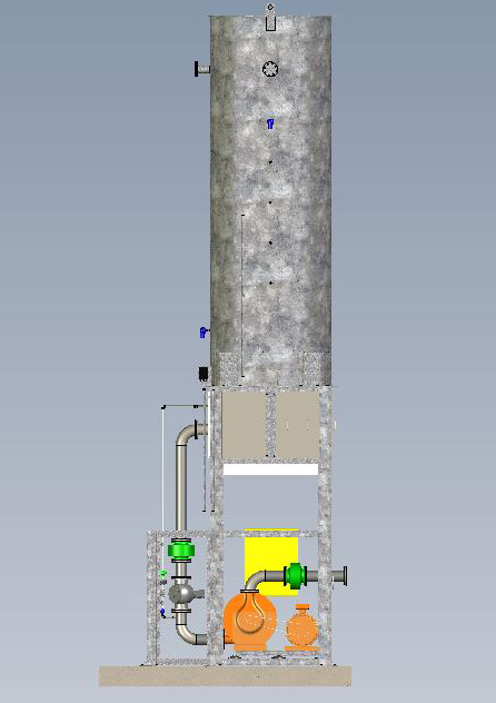
The Liquid Seal will break within second on process upsets.
It’s simple design will be possible for any size of gas flaring.
It does not need any sophisticated instrumentation.
The Liquid Seal would need water available at process Plant
Background
Flare systems are designed to provide for the safe disposal of hydrocarbons that are either automatically vented or manually drawn from process units at refineries. Hydrocarbons must be controlled in a safe and effective manner in the event of an operational upset. Flare systems gather vented gases and combust them to prevent release directly into the atmosphere.
Flare emissions are difficult to characterize and can be dependent on a number of factors such as volumetric flow, velocity, vent gas composition, energy content, combustion efficiency, and ambient wind conditions. 'Vent gas' is defined as any gas directed to a flare, excluding assisting air or steam, pilot or continuous purge gas. Vent gas flow rates to the flare are measured by in-pipe monitors prior to combustion. These vent gas flow rates do not represent a direct measurement of emissions from flares.
Two flare Regulations have been adopted by the District since 2003. The District Board of Directors adopted Regulation 12, Rule 11, Flare Monitoring at Petroleum Refineries, on June 4, 2003; Regulation 12, Rule 12, Flares at Petroleum Refineries, was adopted on July 20, 2005 and amended April 5, 2006.
Regulation 12, Rule 11, Flare Monitoring at Petroleum Refineries
The purpose of this rule is to require monitoring and recording of emission data for flares at petroleum refineries. It requires operators of flares at petroleum refineries to monitor the gases directed to the flare and submit a monthly report containing: 1) the total daily and monthly volumetric flow of the vent, pilot and purge gas, 2) the hourly average molecular weight of the vent gas, 3) composition of vent gas from required sampling, 4) calculated daily and monthly methane, non-methane and sulfur dioxide emissions, and 5) archive images of the flare.
Click here to view Regulation 12-11 Flare Monitoring Data Submittals since 2004.
Regulation 12, Rule 12, Flares at Petroleum Refineries
The purpose of this rule is to reduce emissions from flares at petroleum refineries by minimizing the frequency and magnitude of flaring.
Notification of Flaring: Refinery owners or operators must notify the District as soon as possible, consistent with safe operation of the refinery, if the volume of vent gas flared exceeds 500,000 standard cubic feet (SCF) or 500 lbs. of sulfur in a calendar day.
Flare Minimization Plans: Flaring is prohibited unless it is consistent with an approved 'Flare Minimization Plan' (FMP). FMPs shall include, in part: 1) a detailed description and technical information for each flare, 2) A description of the equipment or procedures implemented within the last five years or planned to reduce flaring, and 3) a description of prevention measures needed to perform certain refinery activities without flaring.
The District conducted public meetings near each refinery to review FMPs and receive public comments. Click here to view the public meeting notice.
On July 16, 2007, following substantial public input, the District approved the FMPs for all five Bay Area refineries.
Click here to view public comments and approved FMPs.
حمل مخازن مربوط به پروژه فلر پتروشيمي جم
بخشي از پروژه فلر پتروشيمي جم شامل مخازن Knock Out Drum- 991 و Knock Out Drum-992 در تاريخ سوم اسفند ماه جاري بارگيري و به محل نصب پروژه فلر در پتروشيمي جم واقع در منطقه ويژه اقتصادي پارس (عسلويه) حمل شد . مشخصات مخازن مذكور 5متر قطر با عدسي كروي , 17 مترطول و60 تن وزن اعلام شده است , طراحي وساخت اين تجهيزات بدليل شرايط كاركرد در دماي طراحي منهاي 51 درجه سانتي گراد و نوع مواد مصرفي (LTCS) و ابعاد مخازن در نوع خود از ويژگي خاص برخوردار هستند .
Flare QRA

|
|
|
Changes to a flare header system can run in the millions. Flare QRA systematically evaluates the risk associated with relief headers and flare systems and helps reduce the costs associated with the perceived need to retrofit existing headers or construct new ones. While PPM® includes baseline flare calculations and can provide a worst-case estimate of the safety of a multiple unit header system, Flare QRA delivers a more realistic analysis of scenarios involving multiple units. Flare QRA uses data from the PPM® database, standard statistical analysis and Monte Carlo methodology to provide an objective assessment of the risk associated with multiple releases to relief header and flare systems (global scenarios). This is accomplished by accounting for existing layers of protection in the facility that would serve to reduce or eliminate relief loads, as well as the expected frequency of the global scenario. Applications:
Key features:
|
The John Zink® Adsorption/Absorption Vapor Recovery System design can be widely applied, however, it is most commonly used to control hydrocarbon vapor emissions at terminals handling petroleum fuel products, such as gasoline bulk terminals.

In this most common configuration, the unit is equipped with two, identical adsorbers, each filled with activated carbon. One adsorber vessel is on-stream in the adsorption mode while the other is off-stream in the regeneration mode. Switching valves automatically alternate the adsorbers between adsorption and regeneration. One adsorber is always on-stream to assure uninterrupted vapor processing capability.
To process the hydrocarbon vapor-air mixture, the mixture first flows up through the on-stream adsorber vessel. There, the activated carbon adsorbs the hydrocarbon vapor, so clean air vents from the bed with minimal hydrocarbon content.
Simultaneously, the second adsorber is being regenerated off-line. The carbon bed regeneration uses a combination of high vacuum and purge air stripping to remove previously adsorbed hydrocarbon vapor from the carbon and restore the carbon's ability to adsorb vapor during the next cycle. The liquid ring vacuum pump extracts concentrated hydrocarbon vapor from the carbon bed and discharges it into a three phase separator that separates the vacuum pump seal fluid, the hydrocarbon condensate and the non-condensed hydrocarbon/air vapors.
The seal fluid is pumped from the separator through a seal fluid cooler to remove the heat of compression from the seal fluid. The seal fluid is then returned to the liquid ring pump. In some applications, such as chlorinated hydrocarbon vapor recovery, other types of vacuum generators can be substituted for the standard liquid ring pump to avoid incompatibility of the vapor with the seal fluid required by the liquid ring pump.
Next, hydrocarbon vapor and condensate flow from the separator to an absorber column section that functions as the final recovery device. The hydrocarbon vapor flows up through the absorber packing where it is subsequently recovered by absorption into a liquid hydrocarbon absorbent. The circulating absorbent supplied from storage serves the dual purpose of absorbing the recovered hydrocarbon vapor and cooling the vacuum pump seal fluid. This absorbent is normally the same hydrocarbon liquid that was the original source of the vapor generation. For example, gasoline product from a storage tank is the absorbent fluid in gasoline vapor control applications. The recovered product is simply returned along with the circulating gasoline back to the product storage tank.
A lean absorbent supply pump and a rich absorbent return pump are provided with the ADAB system to circulate the required absorbent. A small stream of air and residual vapor exits the top of the absorber column and is recycled to the on stream carbon bed where the residual hydrocarbon vapor is re-adsorbed.
 Welcome to my page! I want to share my stuff with you and hope you will find something useful here. I hope you enjoy my collection and come back again and again. I will do my best to make the content ever more interesting. Thank you for your time!my blog in persian,English & Arabic languge.